Looking for some tech savvy members! My dept built a new state-of-the-art HQ that does NOT include a pole or other “cool” traditions from the old days. Bummer. Anyway, we did manage to bring our old Gamewell turtle gongs, tickers etc to the new facility. We have a large oak display cabinet in the day room to display the old helmets gongs etc to the public.
The members are looking to find a way to get he gamewell turtle gong activated again. My department is combined now with the PD and the dispatch center is located in the same building for both depts. The new dispatch “console” was not wired for “the bells” as it was in the old station.
We are looking to get the turtle gong back into service without running wires and relays to the dispatcher console. It would involve breaching concrete walls obtaining power sources etc and the Town is not going to pay for that just to get some bells ringing again.
Does anyone know if there is a “tone activated” DC relay or something that could be wired into the gong to ring once when our station tone is activated? We thought about retro-fitting an old Minitor II and wiring it to a relay or something. The station gong is an early brass Gamewell unit that is 12 inches and uses 12V DC. We’re just looking to get it to “gong” once when the station “tone” hits. Anyone know of any economical way to accomplish this and what hardware will be needed?
Several folks have suggested digging up a used Plectron from the 70's. Others said to wire an old Minitor that will trip a 12v DC circut to ring the bell once. I like this idea best, however I have no idea where the "tone activation" relay may in the Minitor circut board.
Can anyone point me in the right directon here to help acomplish this wiring task? Thanks for the help. Barrington, RI Fire Dept
Gamwell Gong and Minitor wiring help??
Moderator: Queue Moderator
Re: Gamwell Gong and Minitor wiring help??
Minitor
Matching amplified charger base - connector on the back has a contact closure.
Time-delay 12VDC coil relay.
Loop 12VDC in to the base, out to the relay, ground the other side.
When the pager alerts, the relay will fire and then drop after whatever time delay you pick.
Wire big 12VDC through the relay, then out to the bell. Ground the other side of the bell, and you should be golden.
This is a pretty standard configuration - many stations still use similar systems for primary alerting.
If you have a light or some other physical activation (not just speakers) for the new system, you could feasibly use that source to drive a time-delay relay as above, removing the need for the pager.
Re: Gamwell Gong and Minitor wiring help??
Outstanding idea. Where would this "timing" device be located for purchase? I don't even know what it looks like. On the other hand, do you mean use the actual "AC charging base" from the Minitor? Thanks for your time...Jason
Re: Gamwell Gong and Minitor wiring help??
Digikey for the relay... search "time relay". As for the base, there are two types. The regular AC charging base won't work. You need the amplified charger, which has a speaker in the front, antenna connector on the back, and a DIN connector on the back for the contact closure.fiamen55 wrote:Outstanding idea. Where would this "timing" device be located for purchase? I don't even know what it looks like. On the other hand, do you mean use the actual "AC charging base" from the Minitor? Thanks for your time...Jason
Re: Gamwell Gong and Minitor wiring help??
TV thank you very much for your time, I will look into both ideas further.
Re: Gamwell Gong and Minitor wiring help??
Tv when you say DIN connector you mean this is the type of "timer relay" that would be plugged in there? Thnaks
Re: Gamwell Gong and Minitor wiring help??
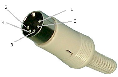
No. A DIN connector is a type of... well, connector. You'll need a male DIN connector (also available from Digikey) to plug into the amplified charger base. See:fiamen55 wrote:Tv when you say DIN connector you mean this is the type of "timer relay" that would be plugged in there? Thnaks
http://www.colmer.info/c64/images/c64dt ... drive3.jpg
The time-delay relay is a completely separate item.
Re: Gamwell Gong and Minitor wiring help??
Take a look at these two pages for some ideas:
http://www.batlabs.com/minitor.html
http://radioetcetera.googlepages.com/fi ... onalerting
Andy
http://www.batlabs.com/minitor.html
http://radioetcetera.googlepages.com/fi ... onalerting
Andy
Re: Gamwell Gong and Minitor wiring help??
Guys the problem I'm having is my own stupidity I'm sure. I have tried tapping into the 2nd and 6the pin on the Minitor II, as suggested, in Batlab with no luck. I do have a relay wired that will trip the bell when I hook it to 2.5 or more volts DC. The pager itself will not trip my relay without a transistor wired in I would suppose. I do have a 2N3904 transistor but have no clue how to wire it in correctly to increase the voltage.
My next suggestion was to wire into the "alert" LED on the pager. Well no luck there either. Just will not trip my relay. I now have obtained a Minitor II Amplified charger base. I purchased a 5 pin DIN connector. According to various websites, all I needed to do was connect my relay to the 2nd and 3rd pin of the DIN connector. No luck. I popped open the amp charger and notice that there is a ground wire below the other 5 pins. I am going to try and connect to the 2nd pin and the ground and see what happens. All the info stated all I needed to do was connect my relay to the 2nd and 3rd pin on this type of charger. But this did not work. There must be something else going on with that ground wire that I mentioned. Any further thoughts? So far everyone has been great with suggestions, thanks a million.
My next suggestion was to wire into the "alert" LED on the pager. Well no luck there either. Just will not trip my relay. I now have obtained a Minitor II Amplified charger base. I purchased a 5 pin DIN connector. According to various websites, all I needed to do was connect my relay to the 2nd and 3rd pin of the DIN connector. No luck. I popped open the amp charger and notice that there is a ground wire below the other 5 pins. I am going to try and connect to the 2nd pin and the ground and see what happens. All the info stated all I needed to do was connect my relay to the 2nd and 3rd pin on this type of charger. But this did not work. There must be something else going on with that ground wire that I mentioned. Any further thoughts? So far everyone has been great with suggestions, thanks a million.
Re: Gamwell Gong and Minitor wiring help??
Didn't I address this in PM?
Assuming pins 2 and 3 are correct (I can't remember), and assuming your relay has a 12VDC coil, do the following:
Obtain a 12VDC power supply (wall wart is fine, or from an existing supply).
Take the positive wire to pin 2.
Take pin 3 to one side of the relay coil.
Take ground from the power supply to the other side of the relay coil.
Current will then flow, closing the relay, when the amp base gets alerted.
Re: Gamwell Gong and Minitor wiring help??
Yes Tv I did PM you and for some reason it popped up here on the general board. I appreciate your suggestion it makes sense and I will try that.
Gamwell Gong and Minitor wiring UPDATE!
Again thanks to all who keep reading my amateur BS probles and continue to offer their time. I do appreciate it. I have finally wire this beast according to everybodys drawings etc. The 2nd and 3rd pin is where I want to be to supply the power for the coil on my relay when the charger contacts activate. Everyone, including myself, have assumed that I have Motorola amp charger model NRN3041A, 3042A, or 3044A. These all have the 6 pin accessory port on back. All the posted lierature clearly shows pin 2-3 as the "dry contact"
Here is the Million Dollar F-up on my part. The Motorola Amp charger I have is Model NLN4985. Yes I do have the accessory port on the back for a DIN connector only it has 5 pins not 6. With this new correct wiring as stated above, I believe that my models pin 2-3 are NOT the dry contacts because the unit will not trip my relay still. Also I get feedback out of the chargers main speaker when I hook DC power to pins 2-3. If we assume 2-3 are open till the tones activate it, there should be no reason to be getting any feedback from the base unit (open closure NO current flowing right!). This is why I think the "dry closure" might be different pins on my charger.
So I'm now trying to find different combinations for this other that just 2-3. Anyone have any pin assignments for this particular unit that isolate where the contact closure is for the NLN4985. Again Thanks for all your time.
P.S. I hope this S^@! isn't on my Lt's test comin' up
Re: Gamwell Gong and Minitor WORKING!
Well after much input from everyone here the bell is ringing again! On this particular model I have the "dry contact closure" are pins 3 and 5. Thanks for all your help.